
DFM Project 3: Injection Molded Sunglasses
This project was really a culmination of my previous two projects: the machining principles and CAM of my first project, the mold design and flow simulation of my second project, and the cumulative hours of both of my previous two projects put together. My biggest takeaways from this project came from creating complex CAD bodies, creating molds and doing mold analysis for parts with non-planar split lines, and learning how to reduce operation time and optimize my finish on multi-hour mill operations.
I spoke a fair bit in DFM project two about my gripes with SOLIDWORKS surface modeling and its quirks. After struggling with it in the last project despite telling myself for almost three years now that I’d spend the time to sit down and really figure it out I decided this would be the project where I’d finally get over my SOLIDWORKS surface hump. I mostly succeeded. If we were to stick to our reference designs our sunglasses design should have been one continuous organic body.


Figure 1. Three images I used for reference images in the creation of my sunglasses design. I did not take any of these photots.
A design like this would have also been easier to accurately recreate on our CNC mills. However, my teammate and I decided to go for a more angular design because it allowed me to make my body as a series of distinct surface shapes which is a modeling technique I have found to have a much higher rate of success than trying to make continuous organic surfaces. I also knew that we were going to machine our mold using primarily ball endmills so many of the hard corners would be removed due to our manufacturing process.
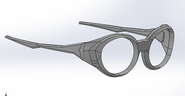
Figure 2. An image of my cad for our glasses design.
After creating my design I then created a mold and started running mold analysis to make sure my part would be manufacturable. From my previous project I was pretty comfortable with placing my split line and making sure that I had proper draft angles and no overhangs. What was new to this project and that took a bit more time was flow analysis for injection molding and clamping force analysis. The biggest mold stock we had was 6” x 4” x 2” and in order to fit a person our glasses needed to be 5.8” wide so the mating faces of our molds at the widest are my frames was quite thin so i was worried I was going to run into issues with the clamping force being insufficient. However, the analysis I performed suggested that there would be enough clamping force and the fact that I had very few instances of flashing with my part seems to suggest that this was indeed the case. The second form of analysis I performed was flow analysis for the flow of plastic into the mold. This was also a concern because the rim of the glasses was quite small and I was concerned if the plastic was going to be able to flow through these bottle necks well enough for the entire mold to fill. Analysis again suggested that this would not be a problem but in retrospect because I couldn’t achieve the full geometry of the design with the endmills we had access to I should have increased these pinch points further as an insurance policy.


Figure 3. My bottom mold half(left), and my top mold half(right)

Figure 4. A screenshot of my final flow simulation that suggests my part should be injectable on the injection molder I had access to within 3.5 seconds.
After the analysis was done, it was time to create my CAM and get to milling. My CAM operations for both halves of my molds consisted of a roughing pass with a shear hog and then finishing with the largest ball endmill that would fit inside the geometry that I was trying to finish. I used Fusion's 3D adaptive clearing toolpath feature for all of my machining, but if I were to do it again I would have switched to more traditional finishing passes like scalloping and parallel, as I likely could have saved some time and ended up with an even better finish.
Figure 5. A video of my CAM setup for the bottom half of my mold. The estimated time to complete this setup was 3 hours 43 minutes. The real machining time was closer to 4 hours 30 minutes.
Figure 6. A video of my CAM setup for the top half of my mold. The estimated time to complete this setup was 5 hours 5 minutes. The real machining time was closer to 6 hours.
Figure 7. A video of some of my machining operations.
My biggest takeaways from the machining process were to always leave some stock to zero off of, and to spend the time to triple-check any decisions you’re making and to physically orient your stock as you want it to mate once it's milled. I learned the importance of always having somewhere to zero off when I had a big scare of losing my zeros four hours into the machining of my top mold. I realized that because I had milled the entire top face of my stock into one organic shape, I had nowhere to accurately re-zero my Z-axis off of. Luckily I didn’t actually lose my Z-zero, but if I were to make any similarly complex mold again, I would leave a pillar of stock somewhere on my mold that had a clean face that I could re-zero all of my axes on. My second big lesson came from when I went to start my second mold half and realized that my pre-machined holes for my locating pins and sprue would not align with the orientation I machined my first mold half with. On my first mold half, I had placed the locating holes in the opposite corners than the extremes of my frames to avoid excessively thin walls. However, I had not taken into consideration that my top mold could not be milled in any orientation like the bottom mold half could be, because the sprue had an asymmetric draft angle and had already been machined into the block. This mistake meant that I had to manually add in new locating pin holes that were close to the widest parts of the glasses anyways. In the future, I will place my blocks together even before machining them to make sure that my planned milling faces would all work.


Figure 8. A picture of my two completed mold halves separated(left) and together(right). Note on the separated mold halves that the top mold on the right has 4 holes for locating pins and two of them are extremely close to the mold cavity for the frames.
The actual injection molding process went quite smoothly, with the first injection being performed by my professor being one of the best I got. It took me some practice to also start getting good injections, but I got there as well. The biggest problem I had was the extremes of the mold not filling because the rims of the glasses were so thin. This was one of my concerns during the design process and I should have just made them big enough that this was not a concern. However, with some practice and making sure the mold was preheated to above 200 degrees Fahrenheit, I was able to get around this problem.

Figure 9. A picture of all the attempts I took at injecting my glasses frames(left). Note google Gemini was used to remove the background in this image in the absence of a lightbox big enough to contain all my attempts.
Figure 10. A video of me operating the injection mold.
Seeing the design in person, there are quite a few changes I would make aesthetically, but for never having made glasses before, I’m happy with the overall design. As for the actual quality of the finished project, I'm very impressed that we were able to achieve such a nice surface finish and that the glasses were injected so well. This project was drastically over-scoped for what the requirements of this project were and the amount of time I had, but ultimately I'm very happy I took on the challenge and feel as though it helped me learn a lot of helpful lessons I would not have otherwise.


Figure 11. A series of photos of the completed glasses. We ran out of time to create lenses so the ones on the image on the right were added on in photo editing softtware.